

Z641H pneumatic flanged gate valve

- sell:021-32051999
- sell:021-32050777
- fax:021-66099555
Details
- Product Introduction
- Service Promise
- Ordering Process
Z641 series pneumatic wedge gate valves are low-stand open-rod gate valves with pneumatic actuators (double-deck cylinders, with cushioning mechanisms) and manual and protective mechanisms (manual and self-locking pneumatic-manual conversion devices). Because of the double-deck cylinder structure, the lift force of the valve is doubled compared with the single-cylinder pneumatic gate valve. This has fundamentally solved the drawback that the valve body of a single cylinder pneumatic valve is wedged and dies. Moreover, because the valve has a buffer mechanism, it can effectively reduce the wear of the sealing surface of the disc car and the valve body caused by the downward impact of the piston when the valve is closed, and at the same time, it can avoid the phenomenon of the brake plate stuck.
In order to cooperate with users to realize operation automation, besides supplying this series of products, the company can also provide cylinder block including bracket separately, which can help users to reconstruct various existing manual gate valves. Pneumatic and manual dual purpose gate valves.
Because of its advanced technology, reliable performance, convenient operation and maintenance, it has been widely used in petroleum, chemical, metallurgical, electric power, marine and other departments as pipeline opening and closing devices to transport gas and liquid media.
Structural features of pneumatic flange gate valves
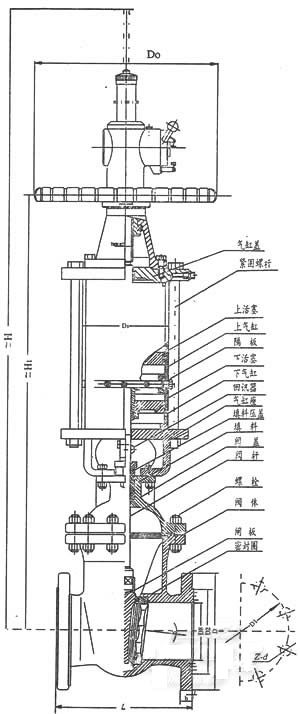
1. The valve is mainly composed of valve body, valve cover, gate plate, valve stem, sealing ring, double-deck cylinder and its piston, piston rod, separator with buffer mechanism, manual mechanism, pneumatic-manual conversion device and valve cover packing device.
2. Upper piston stroke to the upper end of the stroke can be top-up echo, so that it can be sent; lower piston stroke can be top-down echo, so that it can be sent as gate valve open and close information in the central operating room on the analog dashboard display.
3. The rising and falling of the outward indicating rod on the upper part of the handwheel indicates whether the gate of the valve is in the state of lifting or falling. When the gate valve is closed, the extended indicator rod is at the lowest position; otherwise, when the gate valve is fully open, the extended indicator rod is at the highest position. This is the on-the-spot indication for the opening and closing state of the valve.
4, the upper part of the cylinder head is equipped with pneumatic manual conversion device. The switch handle is lifted clockwise to the "pneumatic" positioning hole, and the gate valve is in the pneumatic operating state; otherwise, the switch handle is lifted counterclockwise to the "manual" positioning hole, and the gate valve can be operated manually. The handle of the bevel gear converts to the opposite direction. When the gate valve is operated manually, the hand wheel rotates in the same direction as the ordinary manual valve, that is, turning clockwise to close and turning counterclockwise to open. The opposite is the case with bevel gears.
Main performance parameters of pneumatic flange gate valves
Nominal pressure: 1.6,2.5.4.0.6.4MPa
Usage temperature: -29 ~ 425 C (Tan Gang) -40 ~ + 5 50 C (stainless steel)
Nominal diameter: DN50 ~ 800mm
Body material: 304.306.316L.WCB.HT200
Connection flange: JB/T79.GB913.HG20592
Applicable medium: corrosive fluid such as air, water, steam, oil, nitric acid and acetic acid.
Mode of action: cut off, regulation, manual control.
Supply voltage: 220VAC, 24VAC
Input signal: 4 ~ 20mA/1 ~ 5VDC
0 ~ 20mA/0 ~ 10VDC
Model | Z6S41H-25 | Z6S41H-16 | Z6S41T-10 |
Nominal diameter DN(mm) | 50~600 | 40~400 | 40~400 |
Applicable medium | Water and steam Oil products | Water and steam | Water and steam |
(℃) | 425 | 425 | 200 |
Cylinder working pressure (table) MPa | 0.4~0.6 | ||
Structure principle of pneumatic flange gate valve
This series of products with 0.4-0.6 MPa (surface pressure) to purify compressed air for working pressure, to promote the piston, drive the gate vertical to the fluid displacement, to achieve the purpose of opening and closing the valve.
Ingenious design of double cylinder and buffer mechanism
The working principle of the double-layer cylinder and the buffer mechanism is divided into four stages according to the operation of the gate:
1. Pre-opening stage of gate valve: the piston of upper cylinder (hereinafter referred to as the upper piston) and the piston of lower cylinder (hereinafter referred to as the lower piston) force at the same time, the valve stem in the upper and lower piston, driven by a single piston nearly twice the lifting force, to overcome the maximum static friction between the gate sealing surface and valve body sealing surface, driving the gate plate Rise. Compressed air from the upper cylinder of the lower chamber, through a special channel set in the diaphragm, through the connecting pipe, to the lower chamber of the lower cylinder, driving the upper and lower pistons to work at the same time. The gas in the air chamber on the lower cylinder is passed through another specific channel in the baffle. Unobstructed discharge of cylinders in vitro.
2. The latter stage of gate valve opening: after slightly opening the gate, the lower piston runs to the upper dead point, and the gate continues to lift under the drive of the upper piston until it reaches the full open position.
3. The first stage of the closing of the gate valve: when the upper piston is pushed, the gate will leave the full open position and begin to decline.
4. The latter stage of gate closing: when the upper piston touches the lower piston bump and drives the lower piston to continue to descend together, the downward speed is obviously slowed down due to the obstruction of the inlet passage of the upper air chamber of the lower cylinder and the exhaust passage of the lower air chamber of the lower cylinder, and the gate is lowered to the fully closed position. Slow down the impact of the gate, self-closing the valve, not to make the valve wedge too tight, but also to protect the sealing surface from violent impact and damage. Flexible and reliable pneumatic-manual switching mechanism, pneumatic-manual switching mechanism on the upper part of cylinder head, can easily rotate the operating handle at any position during the opening and closing process of gate valve, directly carry out the switching from pneumatic to manual or from manual to pneumatic operation mode, and the switching operating handle adopts positioning pin. Self locking design, reliable positioning after the handle is positioned. When a fault occurs in the solenoid valve and its control circuit or air supply system, it can be quickly converted to manual operation without any other auxiliary tools to ensure the normal operation of the line and avoid accidents. Before the self-control system of the new project is completed, this series of gate valves can be used reliably as manual gate valves, which are flexible and light in action.
The valve closing time can be adjusted by adjusting the buffer mechanism installed on the diaphragm, and the gate closing time can be adjusted within a certain range.
The valve can be equipped with an electric or pneumatic return device for sending the state information of the valve switch. Therefore, remote control, centralized control and automatic control can be realized by using this valve.
1. The anti-corrosion cylinder of this valve is made of seamless steel tube. The inner surface of the valve is plated with anti-corrosion hard chromium and polished. It has the advantages of low friction, low rust resistance, high hardness and long service life.
2. The sealing ring in the cylinder adopts the 0-shaped sealing ring of NBR. The sealing performance is reliable and the replacement is convenient during maintenance.
Specification for pneumatic flanged gate valves
1. Valve performance
Model | Nominal pressure PN(MPa) | Valve test pressure
PN(MPa) | (℃) | ||||||||
120 | 200 | 225 | 250 | 300 | 350 | 400 | 425 | ||||
强度试验 | 密封试验 | Working pressure P(MPa) | |||||||||
Z6S41T-10 | 1.6 | 2.4 | 1.6 | - | 1.6 | - | 1.5 | 1.3 | 1.2 | 1.0 | 0.9 |
Z6S41H-25 | 2.5 | 3.8 | 2.5 | - | 2.5 | - | 2.3 | 2.0 | 1.8 | 1.6 | 1.4 |
Z6S41H-40 | 4.0 | 6.0 | 4.0 | - | 4.0 | - | 3.6 | 3.2 | 2.8 | 2.6 | 2.2 |
Z6S41H-64 | 6.4 | 9.6 | 6.4 | - | 6.4 | - | 5.7 | 5.2 | 4.6 | 3.8 | 3.6 |
Model | Nominal pressure PN (MPa) | Cylinder seal test pressure PN (MPa) | Cylinder working pressure PN (MPa) |
Z6S41T-10 Z6S41H-25 Z6S41H-40 Z6S41H-64 | 0.6 | 0.6 | 0.4~0.6 |
3. Consumption of gas
[Purified compressed air pressure: 0.4 MPa (table)] One-way air consumption of the cylinder of the gate valve (calculated by the volume of compressed air).
气缸直径D(mm) | 50 | 80 | 100 | 150 | 200 | 250 | 300 | 350 | 400 |
耗气量(m) | 0.0023 | 0.0029 | 0.0033 | 0.0084 | 0.0169 | 0.0198 | 0.0320 | 0.0636 | 0.0707 |
Body, bonnet, valve plate | cast steel |
Sealing surface of valve body and gate | Alloy steel |
Stem | Stainless steel |
Double head bolt | No. 35 steel |
Cylinder | Seamless steel pipe No. 20 |
piston | Cast aluminum alloy |
Hand nut | bronze |
Seal ring | Asbestos rubber sheet Spiral wound metal graphite gasket |
Piston ring and shaft ring | Oil resistant rubber ring |
Stuffing letter | Graphite asbestos rope |

Pneumatic flange gate valve main parts material pneumatic flange gate valve main dimensions
PN1.6MPa external dimensions
DN | D | D1 | D2 | b | f | L | H | Ds | D0 | Z-d | Gas source joint | Kg |
50 | 160 | 125 | 100 | 16 | 3 | 250 | 865 | 160 | 250 | 4-18 | M12×1.25 | 42 |
80 | 195 | 160 | 135 | 20 | 3 | 280 | 1100 | 160 | 300 | 8-18 | 54 | |
100 | 215 | 180 | 155 | 20 | 3 | 300 | 1200 | 160 | 350 | 8-18 | 100 | |
150 | 280 | 240 | 210 | 24 | 3 | 350 | 1380 | 219 | 400 | 8-23 | 135 | |
200 | 335 | 295 | 265 | 26 | 3 | 400 | 1580 | 273 | 400 | 12-23 | 270 | |
250 | 405 | 355 | 320 | 30 | 3 | 450 | 1710 | 273 | 400 | 12-25 | M20×1.5 | 350 |
300 | 460 | 410 | 375 | 30 | 4 | 500 | 1880 | 325 | 500 | 12-25 | 480 | |
350 | 520 | 470 | 435 | 34 | 4 | 550 | 2180 | 426 | 500 | 16-25 | 570 | |
400 | 580 | 525 | 485 | 36 | 4 | 600 | 2325 | 459 | 550 | 16-30 | 900 | |
450 | 640 | 585 | 545 | 40 | 4 | 650 | 2570 | 500 | 550 | 20-30 | 1560 | |
500 | 705 | 650 | 608 | 44 | 4 | 700 | 2800 | 600 | 600 | 20-34 | M24×1.5 | 1820 |
600 | 840 | 770 | 718 | 48 | 5 | 800 | 3010 | 600 | 600 | 20-41 | M27×1.5 | 2850 |
DN | D | D1 | D2 | b | f | L | H | Ds | D0 | Z-d | Gas source joint | Kg |
50 | 160 | 125 | 100 | 20 | 3 | 250 | 865 | 160 | 250 | 4-18 | M12×1.25 | 42 |
80 | 195 | 160 | 135 | 22 | 3 | 280 | 1100 | 160 | 300 | 8-18 | 54 | |
100 | 230 | 190 | 160 | 24 | 3 | 300 | 1200 | 160 | 350 | 8-23 | 105 | |
150 | 300 | 250 | 218 | 30 | 3 | 350 | 1380 | 219 | 400 | 8-25 | 190 | |
200 | 360 | 310 | 278 | 34 | 3 | 400 | 1580 | 273 | 400 | 12-25 | 280 | |
250 | 425 | 370 | 332 | 36 | 3 | 450 | 1710 | 273 | 400 | 12-30 | M20×1.5 | 405 |
300 | 485 | 430 | 390 | 40 | 4 | 500 | 1880 | 325 | 500 | 16-30 | 535 | |
350 | 550 | 490 | 448 | 44 | 4 | 550 | 2180 | 426 | 500 | 16-34 | 720 | |
400 | 610 | 550 | 405 | 48 | 4 | 600 | 2325 | 459 | 550 | 16-34 | 1200 | |
450 | 660 | 600 | 555 | 50 | 4 | 650 | 2570 | 500 | 550 | 20-34 | 1910 | |
500 | 730 | 660 | 610 | 52 | 4 | 700 | 2800 | 650 | 600 | 20-41 | M24×1.5 | 2250 |
600 | 840 | 770 | 718 | 56 | 5 | 800 | 3010 | 730 | 600 | 20-41 | M27×1.5 | 3100 |
DN | D | D1 | D2 | b | f | L | H | Ds | D0 | Z-d | Gas source joint | Kg |
50 | 160 | 125 | 100 | 20 | 3 | 250 | 890 | 160 | 300 | 4-18 | M12×1.25 | 62 |
80 | 195 | 160 | 135 | 22 | 3 | 310 | 1150 | 219 | 350 | 8-18 | 130 | |
100 | 230 | 190 | 160 | 24 | 3 | 350 | 1300 | 273 | 400 | 8-23 | 155 | |
150 | 300 | 250 | 218 | 30 | 3 | 450 | 1450 | 273 | 400 | 8-25 | 240 | |
200 | 375 | 320 | 282 | 38 | 3 | 550 | 1660 | 325 | 500 | 12-30 | M20×1.5 | 280 |
250 | 445 | 385 | 345 | 42 | 3 | 650 | 1860 | 325 | 500 | 12-34 | 305 | |
300 | 510 | 450 | 408 | 46 | 4 | 750 | 2010 | 426 | 500 | 16-34 | 580 | |
350 | 570 | 510 | 465 | 52 | 4 | 850 | 2350 | 459 | 550 | 16-34 | 770 | |
400 | 655 | 585 | 535 | 58 | 4 | 950 | 2530 | 600 | 550 | 16-41 | 1260 | |
450 | 680 | 610 | 560 | 60 | 4 | 1050 | 2780 | 650 | 600 | 20-41 | M24×1.5 | 1680 |
500 | 755 | 670 | 612 | 62 | 4 | 1150 | 3100 | 730 | 600 | 20-48 | M27×1.5 | 2150 |
DN | D | D1 | D2 | b | f | L | H | Ds | D0 | Z-d | Gas source joint | Kg |
50 | 175 | 135 | 105 | 26 | 3 | 250 | 865 | 160 | 250 | 4-23 | M12×1.25 | 85 |
80 | 210 | 170 | 140 | 30 | 3 | 310 | 1170 | 300 | 300 | 8-23 | 125 | |
100 | 250 | 200 | 168 | 32 | 3 | 350 | 1280 | 350 | 350 | 8-25 | 178 | |
150 | 340 | 280 | 240 | 38 | 3 | 450 | 1470 | 400 | 400 | 8-34 | 305 | |
200 | 405 | 345 | 300 | 44 | 3 | 550 | 1650 | 400 | 400 | 12-34 | M20×1.5 | 410 |
250 | 470 | 400 | 350 | 48 | 3 | 650 | 1810 | 400 | 400 | 12-41 | 690 | |
300 | 530 | 460 | 412 | 54 | 4 | 750 | 1960 | 500 | 500 | 16-41 | 770 | |
350 | 595 | 525 | 475 | 60 | 4 | 850 | 2240 | 500 | 500 | 16-41 | 980 | |
400 | 670 | 585 | 525 | 66 | 4 | 930 | 2450 | 550 | 550 | 16-48 | M24×1.5 | 1970 |
The best quality, first-class service Qigao creates more value for you!
"Qigao Valve" expects to continuously improve service quality and strive for excellence. "Sincere service" is the eternal theme of "Qigao". "Qigao" strictly followsIS09001-2000 Quality system certification requirements, strict quality control, responsibility to people, to ensure the healthy operation of production, sales and service. Strengthen communication with users and provide quality products to our customers with perfection and perfect service. Hereby our factory makes the following commitments:
Product Standards:
Products in strict accordance with ChinaGB、HG Standard and USAPISuch as standard design, manufacturing, acceptance. The hardness of the sealing surface meets the requirements of the state and the width exceeds the national standard.
pre-sale service:
Product introduction, technical exchange, non-standard product design, troubleshooting。
Sale service:
A trustworthy contract guarantees timely delivery and keeps in touch with customers. For special or duplicate products, our factory arranges technicians to use and troubleshoot the products for users.
After sales service:
1、"Qigao" brand product quality period is from the factory12In the month, the implementation of the "three guarantees" service (return, replacement, warranty).
2、During the use of our products, our factory regularly organizes technical and quality inspection personnel to visit and consult users for feedback on product quality, usage status and improvement opinions, so as to further improve product quality.
3、Respond quickly to the quality of user complaints, after-sales service personnel rushed to the scene in 24-36 hours (48 hours outside the province).
4、For after-sales service, users are required to fill out the quality feedback information form after the service and make an appraisal opinion in order to improve the service quality of Qigao.
1、If the customer has special requirements for the product, the following instructions must be provided in the order contract.:
a、Structure length;
b、Connection Type;
c、Nominal diameter, full diameter, reduced diameter, pipe size;
d、Operating medium and temperature, pressure range;
e、Tests, inspection standards and other requirements
2、The factory can configure various types of driving devices according to customer's specific requirements.。
3、If the type and model of the valve are determined by the customer, the customer shall correctly state the meaning and requirements of the model and sign the contract under the condition that the supplier and the buyer understand each other.
4、For futures and order customers, please call us in advance to tell the required valve model, specification, quantity, delivery time and location, and timely transfer to the factory account according to the total 30% deposit or full payment. The rest of the payment is pending. Import before shipment to arrange delivery in time.
Order Process:
1、Customer purchase list fax to021-33872143,Or call us 021-33872141
2、Receive customer purchase list, provide valve model selection and quotation (price list)。
3、Specific agreement: delivery date, special requirements, etc.。
download Google:
1、If the customer has special requirements for the product, the following instructions must be provided in the order contract.:
|
|||||
|
|||||
2、The factory can configure various types of driving devices according to customer's specific requirements.。
|
|||||
3、If the type and model of the valve are determined by the customer, the customer shall correctly state the meaning and requirements of the model and sign the contract under the condition that the supplier and the buyer understand each other.
|
|||||
4、For futures and order customers, please call us first to tell the required valve model, specifications, quantity, delivery time and location, and press the total30%The deposit or full payment will be remitted to our factory account in time., The rest of the payment will be remitted before shipment to arrange delivery in time.。
|
Sale service:
Trustworthy contract, guarantee timely delivery, keep in touch with customers at any time。
For special or duplicate products, our factory arranges technicians to use and troubleshoot the products for users.
After sales service:
1、"Qigao" product quality period is from the factory12Month, practice“Three packs”Service (return, replacement, warranty)。
2、During the use of our products, our factory regularly organizes technical and quality inspection personnel to visit and consult users for feedback on product quality, usage status and improvement opinions.,
In order to further improve product quality。
3、Respond quickly to the quality of user complaints, after-sales service personnel24-36Hours (outside the province48Hour) rushed to the scene。
4、For after-sales service, the user is required to fill out the quality feedback information form after the service and make an appraisal opinion in order to improve the service quality of “Qigao”.。
statement |
|